Project ongoing · Robotics
Robotic
We build a robotic arm, from the joint motors all the way to the hand.
- the reducer ratio
- 40:1
- the reach
- 520 mm
- the design load
- 2 kg
- the elbow torque, estimated
- 13.9 N·m
For people who come from robotics and mechatronics engineering, computer science
The arm
A.R.M. is an arm with three degrees of freedom: a base that turns around the vertical axis, a shoulder and an elbow. The upper arm and forearm are 260 mm long each, so the tip reaches 520 mm from the shoulder. The goal is to move 2 kg.
Every joint follows the same layout: a brushless drone motor, a 40 to 1 cycloidal reducer, a magnetic encoder and a driver that controls the current. Precise actuators on the market cost a lot: we build our own, and that way we understand every part.
| Degrees of freedom | 3 | base, shoulder, elbow |
|---|---|---|
| Upper arm | 260 mm | from the shoulder to the elbow |
| Forearm | 260 mm | from the elbow to the tip |
| Reach | 520 mm | |
| Design load | 2 kg | at the tip |
| Base rotation | from −180° to +180° | |
| Shoulder rotation | from 0° to 90° | |
| Elbow rotation | from −90° to +90° | |
| Motors | Tarot 4008 and 4114 | the 4114, bigger, on the shoulder |
| Structure | 3D-printed PAHT-CF | hollow profiles of 20 × 20 mm, 2.5 mm wall |
The cycloidal reducer
A brushless motor spins fast but has little torque. The reducer does the opposite: it slows things down 40 times and multiplies the force, in a disc 60 mm wide.
At the centre there is a cam, offset half a millimetre from the axis. As it turns, it makes two discs with 39 lobes oscillate inside a ring gear with 40 teeth. The discs do not rotate, because eight fixed pins pass through their holes. It is the ring gear that advances, one tooth at every turn of the cam: 40 turns of the motor for one turn of the elbow.
The two discs work 180 degrees apart, so the forces balance out. Many lobes touch the teeth at the same time: this is why a cycloidal reducer has very little backlash and handles shocks well.
| Ring gear teeth | 40 | 2 mm semicircles on a 52 mm circle |
|---|---|---|
| Disc lobes | 39 | diameter from 49 to 51 mm |
| Eccentricity | 0.5 mm | |
| Discs | 2, 5 mm thick | at 180 degrees |
| Disc holes | 8 of 7.08 mm | with 2 bearings each |
| Pins | 3 mm in diameter | the play in the hole is 1 mm, double the eccentricity |
| Bearings | 37 | 2 of 52 mm, 2 of 24, 1 of 18, 32 of 7 |
| Joint size | 60 × 74 mm | diameter by length |
N = 40       ring gear teeth
R = 26 mm    radius of the teeth circle
r = 1 mm     radius of the teeth
e = 0.5 mm   eccentricity

ψ(t) = atan2( sin((1 − N)·t), R/(e·N) − cos((1 − N)·t) )
x(t) = R·cos t − r·cos(t + ψ) − e·cos(N·t)
y(t) = −R·sin t + r·sin(t + ψ) + e·sin(N·t) with t from 0 to 2πHow much force is needed
With 2 kg at the tip and the arm extended, the weight acts as a lever. The further a joint is from the tip, the bigger the moment its motor must withstand becomes: 5.2 N·m at the elbow, 11.4 N·m at the shoulder.
The available torque is the motor's torque multiplied by 40 and by the reducer's efficiency, estimated at 85%. At the elbow there is margin for 2.7 times the load, at the shoulder for 1.3: this is why the shoulder has the bigger motor.
- Elbow 5.2 N·m
- Shoulder 11.4 N·m
The numbers in the chart
| Distance from the tip (mm) | Moment (N·m) |
|---|---|
| 0 | 0 |
| 65 | 1,28 |
| 130 | 2,55 |
| 195 | 3,88 |
| 260 | 5,2 |
| 325 | 6,71 |
| 390 | 8,22 |
| 455 | 9,8 |
| 520 | 11,39 |
The numbers in the chart
| Joint | Torque |
|---|---|
| Elbow (Tarot 4008) | 5,2 su 13,9 N·m |
| Shoulder (Tarot 4114) | 11,4 su 15 N·m |
The control
The control is layered, each layer faster than the one above it. The innermost one regulates the current in the motor, that is the torque: it is field-oriented control, FOC, and it runs inside the driver. Above it are the velocity loop and the position loop.
The rule is to keep every loop 5 to 10 times slower than the one below it. In the Matlab design, the current loop has a bandwidth of 3 kHz, the velocity loop 50 Hz.
Higher up, a Teensy 4.1 computes the inverse kinematics 200 times a second: from the desired position of the tip it works out the base, shoulder and elbow angles, with a closed-form formula, without iterations. An ESP32 receives the commands over Wi-Fi.
- 01
Encoder
AS5048A magnetic, 14-bit: 16,384 steps per turn. It reads a magnet on the shaft, at a distance of one millimetre.
- 02
Driver
ODESC 3.6, two motors per board, open-source ODrive firmware. It runs the FOC and the current limits.
- 03
Teensy 4.1
600 MHz processor: inverse kinematics at 200 Hz, trajectories, workspace limits. It talks to the drivers over CAN.
- 04
ESP32-S3
The supervisor: commands over Wi-Fi, data logging, connection to the Teensy at 3 Mbaud.
- Peak of 16.1% above the setpoint after 0.167 ms
- Within 2% of the setpoint after 0.30 ms
The numbers in the chart
| Time (ms) | Current relative to setpoint |
|---|---|
| 0 | 0 |
| 0,025 | 0,324 |
| 0,05 | 0,616 |
| 0,075 | 0,849 |
| 0,1 | 1,012 |
| 0,125 | 1,11 |
| 0,15 | 1,154 |
| 0,167 | 1,161 |
| 0,2 | 1,141 |
| 0,25 | 1,075 |
| 0,3 | 1,018 |
| 0,35 | 0,989 |
| 0,4 | 0,983 |
| 0,45 | 0,988 |
| 0,5 | 0,995 |
| 0,6 | 1,002 |
| 0,8 | 1 |
| 1 | 1 |
- Peak of 27.6% above the setpoint after 10 ms
- Within 2% of the setpoint after 30.8 ms
The numbers in the chart
| Time (ms) | Velocity relative to setpoint |
|---|---|
| 0 | 0 |
| 1 | 0,25 |
| 2 | 0,481 |
| 3 | 0,686 |
| 4 | 0,859 |
| 5 | 1 |
| 6 | 1,109 |
| 8 | 1,24 |
| 9,99 | 1,276 |
| 12 | 1,25 |
| 15 | 1,156 |
| 20 | 1,012 |
| 25 | 0,964 |
| 30 | 0,976 |
| 35 | 0,997 |
| 40 | 1,005 |
| 50 | 1,001 |
| 70 | 1 |
Guiding it by hand
An arm that works alongside people must also let itself be guided. In simulation the elbow estimates the torque coming from outside, without a force sensor, only from current and movement. Then it changes behaviour: it follows the trajectory, yields when someone pushes it, learns the new position and holds it.
In the test the elbow rises from 0 to 45 degrees in 2 seconds, with a maximum error of one hundredth of a degree. Then a person pushes it up to 15 N·m: the arm yields up to 157 degrees, and when the hand lets go it learns the position at 101 degrees. It holds it with 4.33 N·m.
At 13 seconds a knock shifts it by 25 degrees: in 1.3 seconds it is back in place, within half a degree. The simulation uses the model from the first phase of the project, with a 30 to 1 reducer and two motors on the joint.
- Follows the trajectory from 0 to 45 degrees in 2 seconds
- Yields to the push the person pushes up to 15 N·m
- Learns the position 101 degrees
- Holds it 4.33 N·m, 3.31 A per motor
- A knock returns to within half a degree in 1.3 seconds
The numbers in the chart
| Time (s) | Angle (°) | Reference (°) |
|---|---|---|
| 0 | 0 | 0 |
| 0,5 | 4,65 | 4,66 |
| 1 | 22,5 | 22,5 |
| 1,5 | 40,35 | 40,34 |
| 2 | 45,01 | 45 |
| 2,5 | 45 | 45 |
| 3 | 45 | 45 |
| 3,5 | 45 | 45 |
| 4 | 75,16 | 45 |
| 4,5 | 128,02 | 45 |
| 5 | 155,09 | 45 |
| 5,5 | 152,91 | 45 |
| 6 | 138,5 | 45 |
| 6,5 | 128,14 | 45 |
| 7 | 120,74 | 45 |
| 7,5 | 113,65 | 45 |
| 8 | 97,41 | 97,42 |
| 8,5 | 100,98 | 100,99 |
| 9 | 100,98 | 100,99 |
| 9,5 | 100,98 | 100,99 |
| 10 | 100,98 | 100,99 |
| 10,5 | 100,98 | 100,99 |
| 11 | 100,99 | 100,99 |
| 11,5 | 100,99 | 100,99 |
| 12 | 100,99 | 100,99 |
| 12,5 | 100,99 | 100,99 |
| 13 | 100,99 | 100,99 |
| 13,5 | 75,38 | 100,99 |
| 14 | 91,3 | 91,29 |
| 14,5 | 101 | 100,99 |
| 15 | 101 | 100,99 |
| 15,5 | 100,99 | 100,99 |
| 15,99 | 100,99 | 100,99 |
The numbers in the chart
| Time (s) | Push (N·m) | Estimate (N·m) |
|---|---|---|
| 3 | 0 | 0 |
| 3,2 | 0 | 0 |
| 3,4 | 0 | 0 |
| 3,6 | 0,4 | -0,03 |
| 3,8 | 11,53 | 8,58 |
| 4 | 14,96 | 14,58 |
| 4,2 | 15 | 14,72 |
| 4,4 | 15 | 14,72 |
| 4,6 | 13,95 | 14,02 |
| 4,8 | 11,85 | 11,94 |
| 5 | 9,75 | 9,84 |
| 5,2 | 7,65 | 7,75 |
| 5,4 | 5,55 | 6,18 |
| 5,6 | 4 | 4,31 |
| 5,8 | 4 | 4,27 |
| 6 | 4 | 4,27 |
| 6,2 | 4 | 4,27 |
| 6,4 | 4 | 4,27 |
| 6,6 | 4 | 4,27 |
| 6,8 | 4 | 4,27 |
| 7 | 3,99 | 4,27 |
| 7,2 | 3,89 | 4,2 |
| 7,4 | 3,07 | 3,58 |
| 7,6 | 0,93 | 1,54 |
| 7,8 | 0,11 | 0,45 |
| 8 | 0 | 0,21 |
| 8,2 | 0 | -0,27 |
| 8,4 | 0 | -0,04 |
| 8,6 | 0 | 0,01 |
| 8,8 | 0 | 0 |
| 9 | 0 | -0,01 |
The actuator model
Before building, the team wrote the complete mathematical model of the actuator: the electrical part, the magnetic one, the mechanical one, the transmission and the temperature. There are about 90 parameters, 55 of the first order and 35 of the second.
The test plan measures the parameters that matter most first: resistance, inductance, torque constant, inertia, friction. The others are added only if needed. It is about 16 hours of testing, with less than 200 euros of instruments.
The trajectories are fifth-degree polynomials, with minimum jerk: the arm starts from any velocity and comes to a stop, without jolts.
τ = (t − t0) / T
q(τ) = c0 + c1·τ + c2·τ² + c3·τ³ + c4·τ⁴ + c5·τ⁵

c0 = q0        c1 = v0·T        c2 = a0·T²/2
Δq = qf − c0 − c1 − c2        Δv = −c1 − 2·c2        Δa = −2·c2
c3 = 10·Δq − 4·Δv + 0.5·Δa
c4 = −15·Δq + 7·Δv − Δa
c5 = 6·Δq − 3·Δv + 0.5·Δa
The numbers on this page come from the design and the simulations. Measurements on the real motors are the next step.
Where we are
- First phaseWe wrote the complete mathematical model of the actuator, with about 90 parameters.
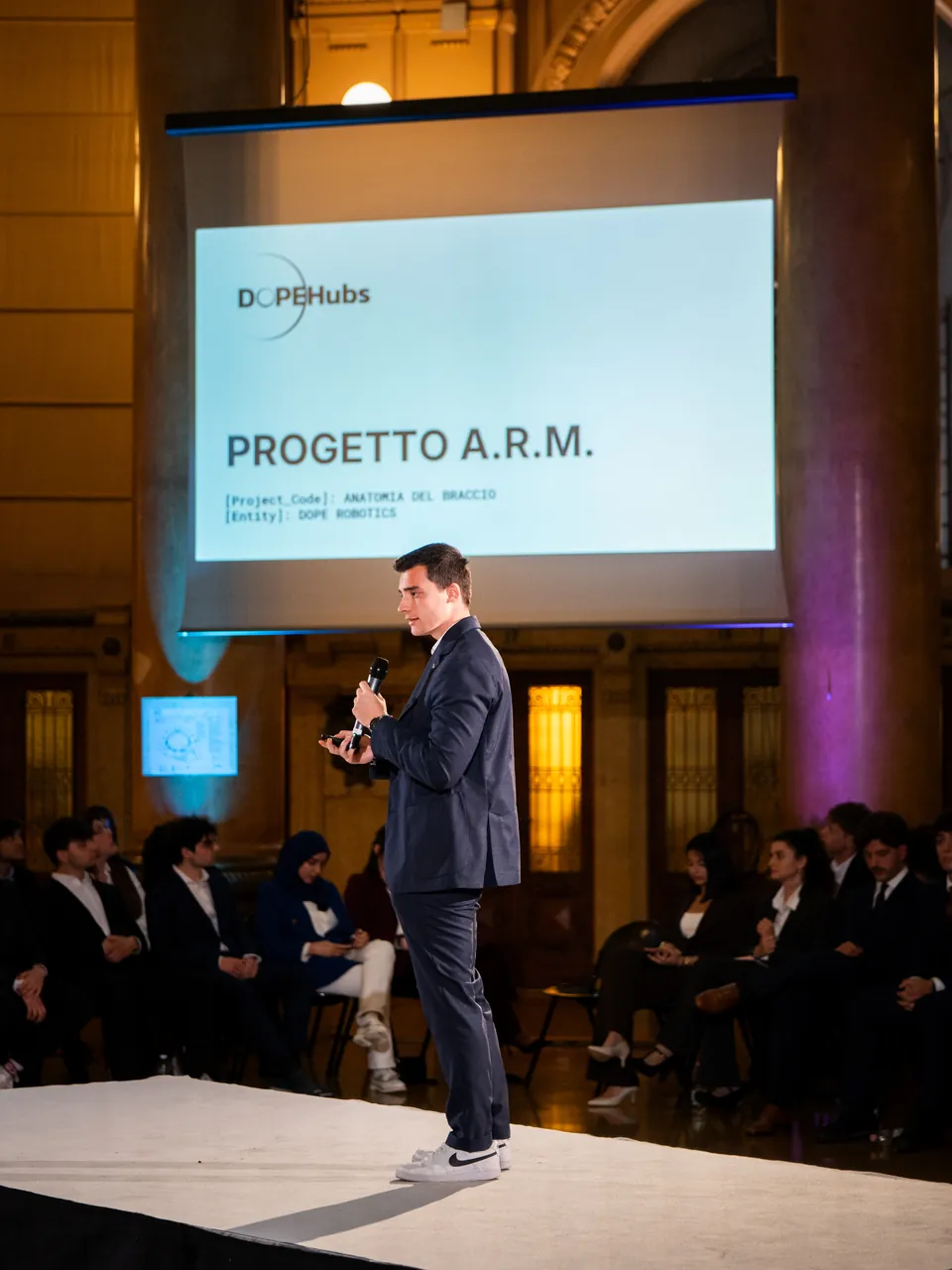
- April 2026We presented the first 3D model of the arm, with a five-fingered hand.
- May 2026In the CAD the elbow joint is ready, second version: Tarot 4008 motor, 40 to 1 cycloidal reducer, magnetic encoder. In simulation the elbow control can be guided by hand.
- Next stepTwo humanoid arms that carry out complex tasks on their own and work alongside people.
Photos
Sources
- Mathematical Modeling and Parameter Reference, version 1.0, January 2026.
- Hardware Characterization, version 1.0, January 2026.
- Analysis of the 3-degree-of-freedom arm, revision 3, March 2026.
- Guide to the FOC parameters and measurement procedures for the Tarot 4008, April 2026.
- Gain design in Matlab and elbow simulation in Python, May 2026.
- CAD of the elbow joint, version 2, 16 May 2026.
- Presentation at the Deep-Tech Showcase, Palazzo della Borsa, 21 April 2026.
Do you want to work on it?
You do not need experience and you do not need a CV. Write to us: we invite you to the next meeting, where you meet the team.